


- 8 March 2024
Keep Your Roof and Gutter in Top Shape with Mitre 10
Roofing and guttering issues are common in many Australian homes, but with the right know-how and tools from Mitre 10, you can easily address and prevent these problems.
Maintaining your roof and gutter system is crucial for protecting your home from water damage and ensuring its longevity. In Australia, where weather conditions can be extreme, regular roof maintenance and gutter cleaning are essential to prevent costly repairs and keep your home safe. This comprehensive guide from Mitre 10 will provide you with expert advice, high-value keywords, and step-by-step instructions on how to maintain your roof and gutters effectively. Whether you’re dealing with gutter guards, gutter cleaning tools, or roof gutter repairs, we’ve got you covered.
Learn how to plan your maintenance tasks, select the right tools, and execute the job like a pro. With the right approach, you can ensure your roof and guttering system remains in top condition, safeguarding your home from the elements.
Plan ahead for Roof and Gutter Maintenance
Roof and gutter maintenance tasks can expose your home to the elements, so it’s crucial to plan your work carefully. Outline the job steps, necessary materials, and tools required. Purchase all items beforehand and create a schedule to manage your time effectively.
Essential Tools for Roof and Gutter Maintenance
METAL ROOF, SPOUTING,
DOWN-PIPES
- Tin Snips
- Hammer
- Cordless Screw-Driver & Hex
- Head Bit
- Drill Bits
- Silicone Gun
- Square
- Pinch Bar
- Hack Saw
- Spirit Level
- String Line
- Pop Rivet Gun
TILE ROOF
Tips to make the job easier
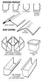
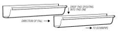
In roof plumbing joins, flashing laps and spouting laps are overlaid and lapped in the direction of the flow of water from the top downwards (Fig. 2).
In some maintenance instances pop rivets will need to be removed. This is done by drilling the pop rivet out with a suitable size drill bit or using a medium sized flat bladed screw driver and hammer and knocking off the head of the rivets. Paint will not adhere to silicone so remove all external traces of silicone with a rag moistened with mineral turpentine.
Spouting maintenance
Step I: Investigating
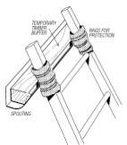
Firstly find out whether the existing spouting profile is available, be carefulthough as what may look the same could in fact be marginally different in size and profile to your existing. It is best to take either a piece of the spouting or one of the spouting clips to your Mitre I0 store. If you are able to match the exact profile then you will not need to remove and replace the spouting clips, unless of course the existing spouting has no fall to the drainage point. Prior to accessing your roof, wrap some cloth around the top of your ladder ends so the spouting does not get scratched. Then place a piece of timber inside the spouting where the ladder is going to be placed so the pressure of weight does not distort the line of the spouting (Fig. 3). Spouting may be available to order at some Mitre 10 stores.
Step 2: Removing existing
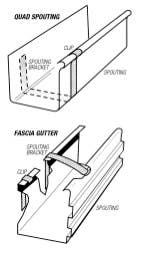
First task is to release the pop rivets which are holding the joins, corners and perhaps the spouting brackets and spouting together. It may be necessary to cut the spouting to facilitate removal, this is done with a hacksaw or tin snips, do not use an angle grinder. The spouting will have been fixed to the fascia board by spouting brackets and nails. To remove the spouting bend the clips at the outer upper lip of the spouting bracket upwards (Fig. 4), then rotate the spouting off the bracket. Remove the spouting clips with your pinchbar.
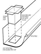
Step 3: Setting out
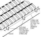
To create water flow to the down-pipe or outlet the spouting needs to be placed out of level, the rate of fall should be around 15-25mm per I0 metres. To create a straight line run a string line out from one end to the other, stretch it tight and check that it has the correct amount of fall with a spirit level (Fig. 5). Place the spouting brackets at one metre spacings using the string line as a guide to the horizontal position. Pre-formed internal and external corners can be purchased for most spouting profiles, however for certain profiles and colours these may need to be made to order, so allow time in your ordering for this. Make a note of where the down pipes are located, and cut and fit the down pipe pops into the spouting prior to putting the spouting up (Fig. 6). Silicone seal between the pop flange and the spouting, press the pop into place and the pop rivet the flanges to the base of the spouting.
Step 4: Fitting the spouting
Commence laying the spouting from the lowest (down pipe end) point, this way the join laps will be layered so the collected water runs over the top of the joins and not into them. Measure along the fascia board for the length of spouting required, add to the length an allowance for a 20mm lap join into adjoining spouting and also the internal or external corners. Cut the spouting to length using your hacksaw or tin snips (do not use an angle grinder). Silicone and join the pre-formed corner to the spouting with pop rivets, use 4 pop rivets per join. Squeeze some silicone around the inside of the overlapping end of any joining spouting. Place the spouting onto the fascia clips and position with the 20mm lap into the adjoining spouting. Press the spouting firmly into place, bend over the restraining tags on the spouting brackets and drill and pop rivet the joins. Clean any excess silicone off the face of the spouting and smooth out any silicone buildup inside the join.
Downpipe maintenance
Step 1: Removal
Remove down pipe clips, and release any pop rivets at joins or the down pipe pop. One section of down pipe should be able to be slid down over the other to free it.
Step 2: Fitting down pipe
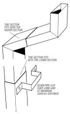
One end of the down pipe is larger in dimension than the other, this is the top section in all instances and allows one piece to fit inside the other and to a certain degree helps length adjustment. Join lap should be a minimum of 40mm. Silicone is not used on the down pipe joins. Commence installation at the top with the spouting, joining and adjusting the length of the eaves bends. Measure, cut and fit the remaining lengths of down pipe. Place a downpipe clip over each join, and secure to the wall with screws or clouts (Fig. 7).
Loose ridge & hip capping tiles
Step 1: Removing & cleaning
Take a bucket up onto the roof with you so all debris can be cleaned as it accumulates. To save breakage of tiles carefully tap the mortar joint between the tile and capping tile with a cold chisel. Once the tile is loose remove the old mortar from all surfaces.
Step 2: Bedding joint
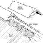
Mix up enough mortar for the job, at the rate of 4 sand, I cement, I limil. Add colour pigment to the mix if needed, this is to be in strict accordance with manufacturers instructions as too much will weaken the bed joint. Add water to create a thick creamy substance. Place some of the mixture in a bucket and take it up on the roof. Mark the outer edge line of the capping tile onto the roof tiles, and with the brickies trowel spread a bed of mortar about 50mm x 50mm along the inside of the marked line. Carefully press the ridge cap into the mortar bed until the correct height has been obtained (Fig. 8), progressively overlap and lay the rest of the tiles. Clean excess mortar off along the edge line of the tiles to leave a full clean bed of mortar.
Chimney flashing
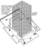
Chimney flashing generally lasts pretty well, but where it needs replacing use the existing flashing as a pattern to either bend up your own from I6 guage zinc alum or galvanized iron, or get some bent for you through your local Mitre I0 store. (Some stores may not offer this service.) The various components of a typical chimney flashing system and how they fit around the chimney are shown in Fig. 9. There is only one correct way to proceed here, and that is in the sequence mentioned in ‘To make the job easier’. The flow of all water must be over the top of all laps, so laying of the flashing must commence at the lower point of the area to be flashed. First install base flashing, ‘ A’ the top lip being pressed into the brick course by 10mm and a bead of silicone to seal this lip to the brick course. Next install side flashings ‘ B’ and ‘ C’, silicone seal the lip into the brick course and silicone and pop rivet the tray overlap to the base flashing. Finally the top rear flashing ‘ D’ is installed, this flashing tucks under the roof tiles and also the top lip fits into the brick course and is silicone sealed. The tray extends out over the top of the side flashings and is silicone sealed and pop riveted for a weather tight seal. Clean off all excess silicone before it dries.
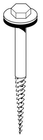
Securing loose metal roof sheets
Corrugated iron sheets fixed down with roofing nails will inevitably become loose over time. The easiest surest way of securing this problem is to remove the offending nail and replace with roofing screws. These are a 50mm long hexagonal headed screw with a rubber washer (Fig. I0). Using a matching driver bit in a cordless drill insert the screw into the hole left by the nail and tighten down securely. In no circumstance put nails or screws in the lower section of the corrugation.
Regular roof and gutter maintenance is vital for the health and safety of your home. By following the expert tips and step-by-step guides provided by Mitre 10, you can effectively address common roofing and guttering issues. Regular inspections, timely repairs, and proper cleaning of your gutters and roof will prevent water damage, extend the life of your roofing materials, and save you money in the long run. Utilising high-quality tools, such as gutter cleaners, gutter cleaning accessories, and roof and gutter silicone, ensures that your maintenance work is done efficiently and effectively.
Additionally, implementing preventive measures like installing gutter guards and using gutter mesh can significantly reduce the frequency of maintenance required. Whether you’re dealing with metal roofing, tile roofing, or any other roofing materials, Mitre 10 has the products and expertise to help you maintain your home’s exterior.
Don't forget to explore our wide range of guttering products, from plastic guttering to timber fascia boards, designed to meet all your home improvement needs. For more detailed guidance and product recommendations, visit our Mitre 10 stores or check out our online resources. Keep your home in top shape with Mitre 10 – your partner in home improvement and maintenance.